Altronix DPS5 Installation Instructions User Manual

Browse online or download User Manual for Accessories for electrical Altronix DPS5 Installation Instructions. Altronix DPS5 Installation Instructions User Manual

  • Download
  • Add to my manuals
  • Print
  • Page
    / 2
  • Table of contents
  • BOOKMARKS
  • Rated. / 5. Based on customer reviews
Page view 0
Overview:
DPS5 power supply/charger converts low voltage AC input into 6VDC, 12VDC or 24VDC @ 4 amp of continuous
supply current (see specifications). This general purpose power supply has a wide range of applications for access
control, security and CCTV system accessories that require additional power.
Specifications:
6VDC-12VDC-24VDC selectable output.
•4 amp continuous supply current at 6VDC-12VDC-24VDC*.
Filtered and electronically regulated output.
Built-in charger for sealed lead acid or gel type batteries.
Maximum charge current 300mA.
Automatic switch over to stand-by battery.
Battery short circuit protection (circuit breaker).
Thermal overload and short circuit protection.
AC input and DC output LED indicators.
Extremely compact design.
Includes battery leads and Snap Trac (Altronix model #ST3).
Board Dimensions: 3.5”L x 2.75”W x 1.75H
* Specified at 25˚ C ambient.
Voltage Output/Transformer Selection Table:
Output Voltage Switch Position Transformer Requirements
12(Recommended Altronix Part #’s)
6VDC Closed Open 16VAC / 40VA (TP1640)
12VDC Open Open 28VAC / 100VA (T2885 or T24130)
24VDC Open Closed 28VAC / 175VA (T28140)
Note: Transformers with higher ratings may be used for all output voltages above as long as you
do not exceed 28VAC or 45VDC.
Installation Instructions:
The DPS5 should be installed in accordance with The National Electrical Code and all applicable Local Regulations.
1. Mount the DPS5 in desired location.
2. Set DC output voltage with switches (refer to Voltage Output/Transformer Selection Table).
3. Connect proper transformer to terminals marked [AC] (refer to Voltage Output/Transformer Selection Table).
Use 18 AWG or larger for all power connections (Battery, DC output).
Keep power limited wiring separate from non-power limited wiring (115VAC / 60Hz Input, Battery Wires).
Minimum .25” spacing must be provided.
4. Measure output voltage before connecting devices. This helps avoid potential damage.
5. Connect devices to be powered to terminals marked [+ DC ---].
6. When the use of stand-by batteries are desired, they must be lead acid or gel type.
Connect battery to terminals marked [+ BAT --- ] (battery leads included).
Use two (2) 12VDC batteries connected in series for 24VDC operation.
Note: When batteries are not used a loss of AC will result in the loss of output voltage.
LED Diagnostics:
Red (DC) Green (AC) Power Supply Status
ON ON Normal operating condition.
ON OFF Loss of AC, Stand-by battery supplying power.
OFF ON No DC output. Short circuit or thermal overload condition.
OFF OFF No DC output. Loss of AC. Discharged or no battery present.
DPS5 - Power Supply/Charger
Rev. 092501
Page view 0
1 2

Summary of Contents

Page 1 - DPS5 - Power Supply/Charger

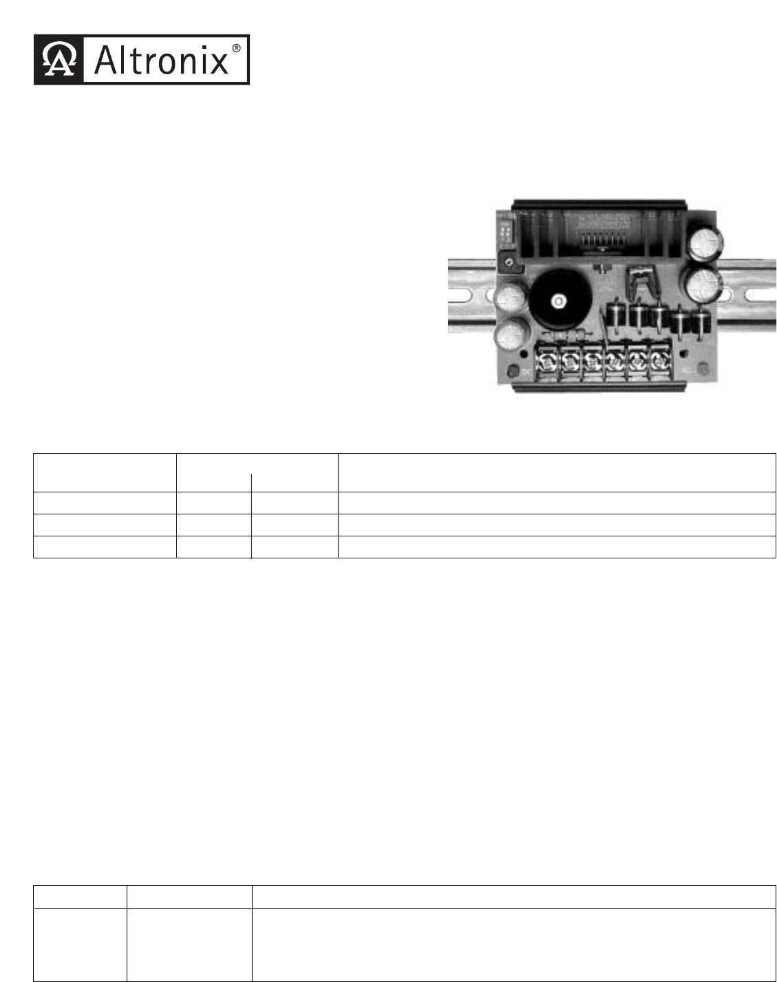
Overview:DPS5 power supply/charger converts low voltage AC input into 6VDC, 12VDC or 24VDC @ 4 amp of continuous supply current (see specifications).

Page 2 - IIDPS5 J30C

Terminal Identification:Terminal Function/DescriptionLegendAC/ AC Low voltage AC input (refer to Voltage Output/Transformer Selection Table).For 6VDC

Comments to this Manuals

No comments