- 4 - NetWay8M/NetWay16M
1g Illuminatedmasterpowerdisconnectcircuitbreaker(switch):
• OFFpositionCircuitbreakertrippedSwitchnotilluminated.
• RESET(ON)positionSwitchilluminated.
1h IEC320Connector:115VAC60Hz(groundedlinecordincluded).
Installing a NetWay1512 adapter for 12VDC IP cameras up to 13W:
1. Mount NetWay1512 in proximity to IP camera (Fig. 2, pg. 4). Affix one side of velcro (supplied) to NetWay1512
and the place the second side of the velcro in the desired location.
2. Connectstructuredcablefromportmarked[IN]on
NetWay1512toanyportsmarked[OUT]ofNetWayM
(Fig. 2, pg. 4, Fig. 1a, pg. 3).
3. Connectstructuredcablefromportmarked[OUT]on
NetWay1512 to the IP camera (Fig. 2, pg. 4).
4. Connect12VDCoutputfromNetWay1512terminals
marked[---12VDC+]tothepowerinputofthe
IP camera (Fig. 2, pg. 4). Polarity must be observed.
5. PowerLEDindicatorwillilluminateonNetWay1512
under normal conditions (Fig. 2, pg. 4).
Installing a NetWay3012 adapter for 12VDC IP PTZ up to 25W:
1. Mount NetWay3012 in proximity to IP camera utilizing mounting hole (Fig. 3, pg. 5).Useaproperfastenerand/or
wall anchor when securing NetWay3012 to the wall.
2. Connectstructuredcablefromportmarked[IN]onNetWay3012Mtoportsmarked[OUT]ofNetWayM
(Fig. 3, pg. 5, Fig. 1a, pg. 3).
3. Connectstructuredcablefromportmarked[OUT]onNetWay3012MtotheIPfixedorPTZcamera(Fig. 3, pg. 5).
4. Connect12VDCoutputfromNetWay3012terminalsmarked[+12VDC---]tothepowerinputofthe
IP camera (Fig. 3, pg. 5). Polarity must be observed.
5. PowerLEDindicatorwillilluminateonNetWay3012undernormalconditions(Fig. 3, pg. 5).
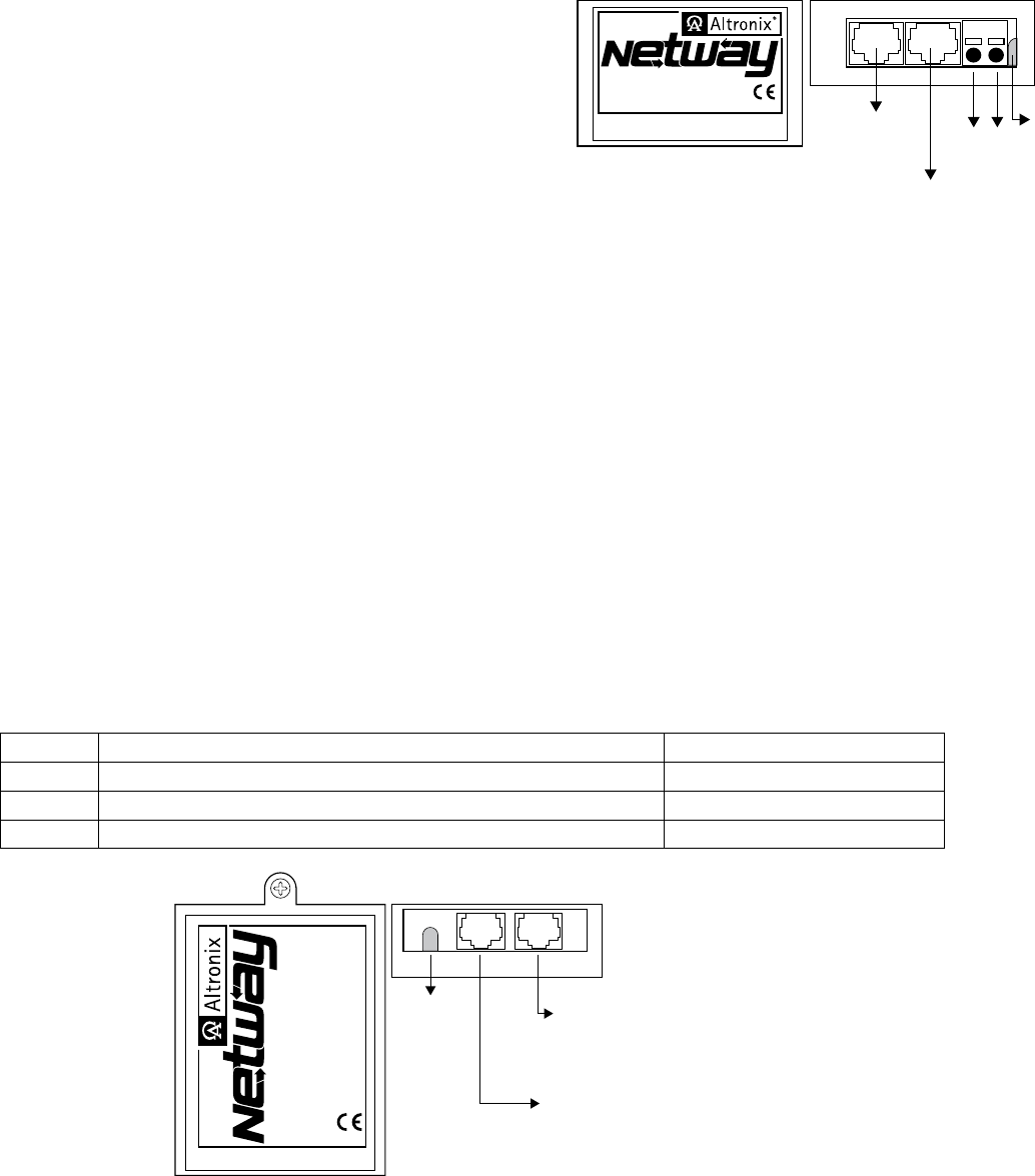
Installing NetWayXT repeater module:
1. Mount NetWayXT in desired location utilizing the mounting hole (Fig. 3, pg. 4).Useaproperfastenerand/orwall
anchor when securing NetWayXT to the wall.
2. Connectstructuredcablefromportmarked[OUT]onNetWayMtoportmarked[IN]onthe
NetWayXT (Fig. 3, pg. 4, Fig. 1a, pg. 3).
3. Connectstructuredcablefromportmarked[OUT]onNetWayXTtothePoEcamera/edgedeviceornextNetWayXT
repeater (Fig. 3, pg. 4).
4. PortstatusLEDswillilluminateonNetWayXTindicatingtheportisoperational(refer to LED definitions on pg. 4).
5. PowerLEDwillilluminateindicating12VDCoutput(Fig. 3, pg. 4).
Port LED definitions for NetWayXT repeater:
Status GreenLED YellowLED
OFF Indicatesitisconnectedas10Base-Tornolink. Indicatesnolink.
ON Indicatesitisconnectedas100Base-TX. Indicatesalink.
Blinking --------------------------- Indicates activity.
Fig. 3 - NetWayXT
NetwayXT
Repeater
www.altronix.com
IN
OUT
Power
LED
Structured
Cable from
NetWayM
Structured Cable
from IP Camera/
Edge Device
or next
NetWayXT
www.altronix.com
IN
OUT
Netway1512
Adapter
12VDC
--- Output +
-- +
12VDC
Output
Structured
Cable from
NetWayM
Structured Cable
from IP Camera/Device
Powe
LED
Fig. 2 - NetWay1512
 Manymanuals.com
 Manymanuals.de
 Manymanuals.fr
 Manymanuals.it
 Manymanuals.pl
 Manymanuals.cz
 Manymanuals.es
 Manymanuals-pt.com
Comments to this Manuals